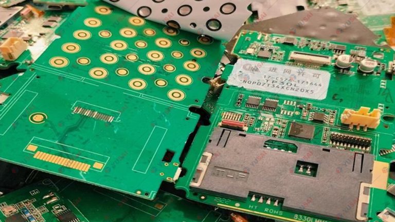
Gold-plated scrap differs greatly from bulk gold-bearing solid waste. Gold only exists as a thin surface plating layer on gold-plated components. After stripping the gold coating, most base substrates can be recycled and reused, which makes the recovery flow distinct from processes for gold embedded inside solid materials.
The mainstream commercial stripping technologies include lead melting stripping, thermal expansion differential stripping, chemical stripping and electrolytic stripping. Below is a detailed introduction to each process.
1. Chemical Stripping Method
Chemical stripping selectively dissolves the surface gold layer with chemical reagents while minimizing corrosion to base substrates. Gold dissolved in the solution is then reduced or electrowon into metallic gold. Common routes are iodine‑potassium iodide stripping, nitric acid stripping, sodium cyanide‑m-nitrobenzene sulfonate stripping and aqua regia stripping.
1.1 Iodine‑Potassium Iodide Stripping
Halogen and halide mixtures can dissolve gold. Chlorine‑hydrochloric acid, iodine‑potassium iodide and bromine‑potassium bromide systems are all capable of gold leaching. The bromine‑potassium bromide route carries high hazards and poor controllability, so chlorine and iodine systems are preferred for precious metal digestion. The iodine system is easier to operate.
Gold dissolution reactions: 2Au + I₂ → 2AuI AuI + KI → KAuI₂
The complex KAuI₂ can be reduced by iron scraps, zinc powder, sulfur dioxide, oxalic acid, formic acid or hydrazine hydrate. Activated carbon adsorption and cation resin exchange are also available for gold separation. Sodium sulfite reduction is recommended for easy solvent regeneration. After gold precipitation, iodide ions in the barren solution are oxidized by sodium chlorate under acidic conditions to regenerate elemental iodine: 2I⁻ + ClO₃⁻ + 6H⁺ → I₂ + Cl⁻ + 3H₂O
Iodine regeneration cuts chemical consumption and eliminates wastewater pollution from waste iodine discharge. The process is simple and well‑controlled; base substrates can be recovered intact with careful operation.
Optimized operating parameters:
- Leach solution: Iodine 50–80 g/L, potassium iodide 200–250 g/L
- Single stripping cycle: 3–7 min; repeat stripping 3–8 times according to coating thickness
- Gold precipitation: reduction by sodium sulfite
- Regeneration conditions: sulfuric acid 15 vol% of barren solution, sodium chlorate ~20 g/L
After gold reduction, the pregnant solution needs hydrolysis treatment to remove impurities before iodine regeneration. Recrystallized iodine can be purified and returned to the leaching circuit.
1.2 Nitric Acid Stripping
Large volumes of gold-plated electronic housings, bases and lead frames are generated in electronics manufacturing. Substrates are typically Kovar alloy (Ni28%, Co18%, Fe54%) or pure copper. Nitric acid selectively strips gold plating, and the stripped substrates can be further processed to recover copper, nickel and cobalt.
1.3 Sodium Cyanide‑m‑Nitrobenzene Sulfonate Stripping
- Solution preparation: Dissolve 75 g NaCN and 75 g m‑nitrobenzene sulfonate into 1 L water.
- Operation: Heat the stripping bath to 90 °C. Immerse gold-plated scrap for 1–2 min until gold dissolves into the solution. Prepare fresh stripping solution once gold saturation slows stripping efficiency.
- Post‑treatment: Rinse stripped parts three times with deionized water and collect rinse water. Dilute spent stripping liquid at 1 part solution to 5 parts deionized water, adjust pH to 1–2 with hydrochloric acid inside a fume hood to prevent HCN poisoning.
- Gold cementation: Use zinc plate or zinc wire to displace gold until the solution loses its yellow colour. Siphon supernatant, wash gold powder 2–3 times and boil with sulfuric acid to remove zinc and impurities. After cleaning and drying, gold powder is melted and cast into crude gold ingots.
Electrowinning is an alternative for gold recovery from cyanide stripping solution. After electrowinning, replenish NaCN and m‑nitrobenzene sulfonate to recycle the bath. Electrowinning greatly reduces cyanide discharge and supports closed‑loop circulation for environmental protection.
2. Lead Melting Stripping
Electrolytic lead is melted and heated slightly above its melting point of 327 °C. Gold-plated scrap is immersed into molten lead; gold diffuses and dissolves into lead. The stripped solid parts are taken out, and gold‑bearing lead is cast into precious lead plates. Gold is then recovered via cupellation or electrolysis.
For cupellation: Add silver to precious lead according to gold content, then cupel to obtain gold‑silver alloy. Quench the alloy into granules and separate gold from silver by nitric acid parting. Gold powder is smelted and cast into crude gold ingots.
3. Thermal Expansion Differential Stripping
This process takes advantage of the mismatch of thermal expansion coefficients between gold plating and base alloy. Heating creates micro gaps between coating and substrate, followed by boiling in dilute sulfuric acid to fully detach gold layers.
Process flow: Heat 1 kg transistor scrap at 800 °C for 1 h, cool down, then transfer into an acid tank with 6 L of 25% sulfuric acid and boil for 1 h to peel gold plating. Sulfate precipitates form simultaneously. After cooling, dilute the slurry to dissolve sulfate salts and separate solid residue by decantation. The solid fraction contains gold powder, silicon fragments and impurities. Dissolve solids with aqua regia, concentrate, dilute and filter. Gold in filtrate is cemented by zinc powder or reduced by sodium sulfite. Acid washing yields gold product with 98% purity.
4. Electrolytic Stripping Method
Thiourea and sodium sulfite form the electrolyte; graphite serves as cathode while gold-plated scrap acts as anode. During electrolysis, gold on the anode is oxidized to Au(I), which immediately forms the soluble complex cation Au[SC(NH₂)₂]₂⁺ with thiourea adsorbed on gold surface. Au(I) is then reduced by sodium sulfite in the electrolyte and precipitates as gold sediment at the tank bottom. Gold concentrate is separated and purified for pure gold production.
- Electrolyte composition: thiourea 2.5 %, sodium sulfite 2.5 %
- Electrodes: central graphite anode roller (φ30 mm × L50 mm); parallel graphite cathodes on both sides (φ50 mm × L400 mm)
- Tank & drum: PVC welded electrolytic cell, effective volume 164 L; perforated PVC hexagonal rotating drum (3 mm holes) for material turnover and liquid exchange
- Operating parameters: current density 4 A/dm², cell voltage 4.1 V, electrolysis time 20–25 min (adjusted by coating thickness and electrode area ratio)